Ring Buffers: High Performance IPC
In this blog, learn more about the theory, and practical implementation, of Ring Buffers in Java within the low-latency audio team at Global.
The Context
At Global, we serve live audio for a multitude of brands all across the UK. These include, but are not limited to: Capital, Heart, LBC, Radio X and Classic FM. On a normal day, our servers can reach peak listener counts in the hundreds-of-thousands, with many processes in the end-to-end journey for a listener having strict real-time deadlines.
Real-time deadlines, in terms of our domain, are tasks that need to be completed from somewhere between a few hundred milliseconds, to a few seconds. If we fail to complete one of these tasks before the deadline it will either cost Global a loss in reputation, or a loss in revenue. Alongside tasks we need to complete in order to meet active deadlines, we also have a variety of reporting and computationally intensive tasks we must complete within a reasonable amount of time after an event occurs.
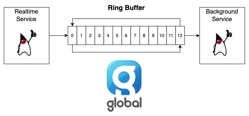
This is what drives the need for Ring Buffers; we need a way of messaging a background process without the need to lock or synchronise with it, and the cost of sending a message must never disrupt the process invoking the request. i.e. sending the message should not cost the sender any significant slowdown resulting in not hitting the realtime deadline.
These latency goals are what rule out the use of a message queue with a locking mechanism, as with any lock acquisition you can cause your current thread (process) to be unscheduled from the CPU. This can result in cache disruption and spikes in page reads, before we start thinking about the pauses introduced by waiting for a lock.
To formally define a Ring Buffer for this use case, we would say:
A Ring Buffer provides a low-latency message queue for inter-process-communication (IPC), allowing 2 or more processes or threads to communicate on the same machine without the need to lock or synchronise with each other.
Hopefully, this provides a good amount of context as to when to use a Ring Buffer, and the sort of requirements we have. Now, let’s dive into how Ring Buffers make this all possible.
The Theory
A Ring Buffer, for our purposes, can be thought of as a circular queue of bytes (Figure 2).
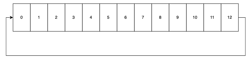
We move through the ring buffer in one direction, reading and writing messages to the 12 bytes available (small for this example). For instance, a producer may write a message to byte 0 then move to byte 1 and so forth. Then another process, acting as the consumer, will follow behind the producer as fast as it can, consuming the messages written. When the producer gets to byte 12, it wraps back around again to byte 0 and continues writing.
For this to work, we need to know 2 key bits of information:
- the tail position: where the producer currently is within the ring buffer. This is where the next message will be written. It is very important the producer does not overlap the head position, as it will then overwrite a message that the consumer has not had a chance to read yet.
- the head position: where the consumer currently is within the ring buffer. This is the position of the next message to be read. It is very important the head position does not overlap the tail position, or it will read data in the buffer that may not have been fully written.
Lets update our diagram to add these concepts (Figure 3):
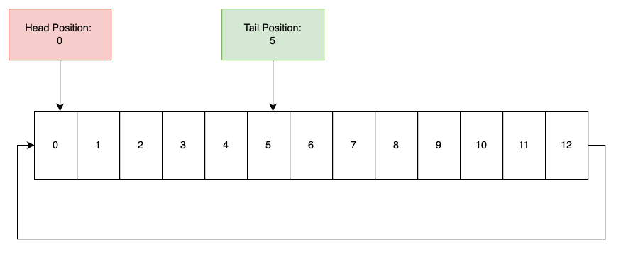
You can see the consumer (at the head position) is at byte 0 in the buffer, whereas the next message to be written would go in byte 5 (the tail position). This means the consumer is behind the producers by 5 bytes (it can go from byte 0 to 4) before it needs to wait for the next message to be created.
The head and tail position is stored outside the buffer itself, in a bit of static memory, of which the location is known to all threads interacting with the buffer.
Now, this example works nicely when we talk about single bytes being written, but in reality we want to encode full (and often complex) messages into the buffer. To achieve this, we need to add one final layer of complexity to the ring buffer; the idea of message length.
To do this, the producer always prefixes messages it writes with some metadata, telling the consumer how long the message it’s written is (Figure 4).
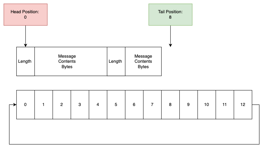
With this, we have changed nothing about the underlying ring buffer itself, it is still just a series of bytes with a head and tail position. However, we now assume that at the beginning of any message we use a single byte within the buffer to tell the consumer how many bytes of the ring buffer to read in order to consume this message in full.
Lets recap:
- a ring buffer is a series of bytes, where we wrap back to the beginning when we run out of space.
- there is a head position (where the consumer is currently at), and a tail position (where the next message can be written to).
- each message contains the length of the message at the start to inform the consumer of how many bytes to consume to read a complete message.
This is all there is fundamentally to a ring buffer, however the tricky part comes when we start thinking about how multiple threads may interact with this memory.
Continue to read the full blog on Global’s website here.